Block diagram reduction is done to obtain transfer
function of the whole system. Lets understand the reduction process by taking
an example.
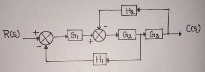
Consider the block diagram shown in the figure below.
Lets simplify it step-by-step using block diagram reduction rules.

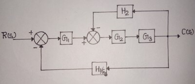
Step-1 :- Use rule 4 for
shifting take-off point after block G3 .

Step-2 :- Use rule 1 for
blocks G2 and G3 .

Step-3 :- Use rule 6 for
loop containing blocks G2G3 and H2 .

Step-4 :- Use rule 1 for
blocks G1 and G2G3/(1+ G2G3H2) .

Step-5 :- Finally, use
rule 6 to get simplified block diagram.

Therefore, the
transfer function of the system is

Note:- You may have noted that block diagram reduction is done by starting at the innermost loops and moving towards outer loops.
The block diagram reduction process can be tedious and time consuming for complicated systems. Therefore, to overcome this drawback, signal flow graph is used.
The block diagram reduction process can be tedious and time consuming for complicated systems. Therefore, to overcome this drawback, signal flow graph is used.


